1、Electronic Detonator Module
- Scope of Application
The NKM-APH12S (NK10) industrial electronic control module is equipped with a dedicated NK10 detonator chip, serving as a high-performance control core specially designed for electronic detonators. Adopting integrated technology to achieve multiple technological breakthroughs, the module is widely applicable to various blasting operation scenarios, including open-pit blasting, tunneling blasting, demolition engineering and mining exploitation.
- Technical Parameter Table
| Item | Parameters | Remarks | |
| Product Model | NKM-APH12S(NK10) | ||
| Dimensions | Outer Diameter (mm) | ≤6.0 | See drawings for details |
| Length (mm) | ≤ 36.8 (Excluding terminals: ≤ 33.8) | ||
| Energy Storage Capacitor | Type | TG4X9-80 | |
| Specifications | Solid-liquid hybrid capacitor 80uF/25V | ||
| Delay Time | Delay Setting Method | On-site programming | |
| Maximum Setting Delay | 12000ms | ||
| Minimum Setting Delay Interval | 1ms | ||
| Delay Accuracy | For delay time < 200 ms: error ≤ ±0.75 ms- For delay time 200–1000 ms: relative error ≤ ±1%- For delay time > 1000 ms: relative error ≤ ±0.5% | ||
| Electrical Parameters | Operating Voltage | -24V~﹢24V | |
| Operating Voltage | ≤30uA | ||
| Overvoltage Protection Threshold | ≥28V | ||
| Undervoltage Protection Threshold | ≤6V | ||
| Ignition Element | Type | Energetic Resistor | 60mJ |
| Resistance | 8Ω ± 20% | Directly inserts into the primary explosive for initiation; no primer needed | |
| Safety Voltage | Safety Voltage Range | Maximum non-firing current > 100mA; Reliable firing voltage < 15V | |
| Lead Terminal | Terminal Specification | M-thread lead terminal | |
| Data Storage | BID | 4 Byte | |
| UID | 7 ByteComposed of 14-digit numbers or letters A–F | ||
| Detonation Password | 4 ByteComposed of 8-digit numbers or letters A–F | ||
| Delay | 2 Byte | ||
| Communication | Communication Voltage / Current | 9V / 19mA (typical value) | |
| Number of Units Supported | 500 detonators (per single blasting machine) | ||
| Communication Distance | ≤ 1000 m (at 120Ω) / 10 m lead wire | ||
| Variable-Frequency Communication | Supports variable-frequency communication to meet higher communication requirements | ||
| Charging | Charging Voltage / Current | 23V / 3.3mA (typical value) | |
| Discharging | Active Discharge Parameters | The maximum charging voltage drops to ≤ 2V within 5 seconds | |
| Passive Discharge Parameters | The maximum charging voltage drops to ≤ 2V within 5 minutes | ||
| Compliance Standards | Production & Inspection | WJ/T 9085-2024 | |
| Field Application | GB6722—2014 | ||
| Information Management | GA1531-2018 | ||
| Operating Environment | Humidity | Relative humidity: 20% ~ 75% | |
| Atmospheric Pressure | 70~106 KPa | ||
| Operating Temperature | -40℃~85℃ | ||
| Storage Temperature | 5℃~35℃ |
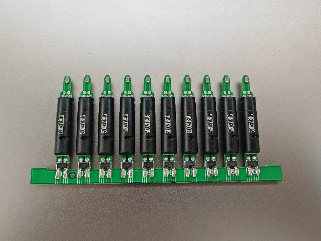
Module Image:
2、
Blasting Machine
- Main Components and Interface Description
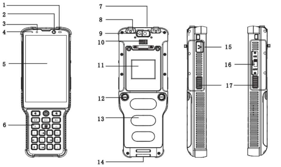
| 1、Light Sensor | 10、Speaker |
| 2、Front Camera | 11、Blasting Control Card Compartment Cover |
| 3、Function Indicator Light | 12、Hand-Tightening Screw |
| 4、System Indicator Light | 13、Battery Compartment Cover |
| 5、Touch Display Area | 14、Type-C Interface |
| 6、Main Keyboard | 15、Cascade Interface |
| 7、Scanning Window | 16、Safety Switch |
| 8、Scanning Window | 17、Scan Button |
| 9、Rear Camera |
- Function Introduction
After successful login, the user will directly enter the home page functional interface.
The functions on the home page are described as follows:
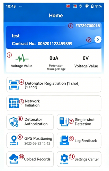
| No. | Function Name | Description |
| ① | Device Number | Displays the current device number for easy identification by the user. |
| ② | Project Management | Manages projects and contracts, used for blasting authorization download. |
| ③ | Device Status | Displays the current device status (including no-load disconnection, current value, and voltage value). |
| ④ | Detonator Registration | Scans detonators to be networked and sets their delay times. |
| ⑤ | Network Blasting | Performs quantity scanning, authorization verification, charging and detonation operations on detonators to be blasted. |
| ⑥ | Detonator Authorization | Downloads the authorization work code for the detonators to be blasted. |
| ⑦ | Single Detonator Test | Performs functional testing on a single detonator. |
| ⑧ | GPS Positioning | Displays current positioning information and compares authorized GPS coordinates to indicate allowed/prohibited blasting areas. |
| ⑨ | Log Feedback | Records the device’s operation and feedback information. |
| ⑩ | Upload Records | Records and views data of completed blasting operations and uploaded data. |
| ⑪ | Settings Center | Used for device upgrade operations, as well as viewing and setting other auxiliary functions. |
3、IoT Platform
- Platform Overview
The Blasting IoT Platform is a comprehensive management platform specifically designed for the blasting industry. It aims to provide accurate, efficient, and convenient digital solutions for the full life cycle of blasting operations.
The main functions of the platform include blasting enterprise management, blasting personnel management, blasting machine management, blasting record management, blasting machine version management, etc. Through full-process
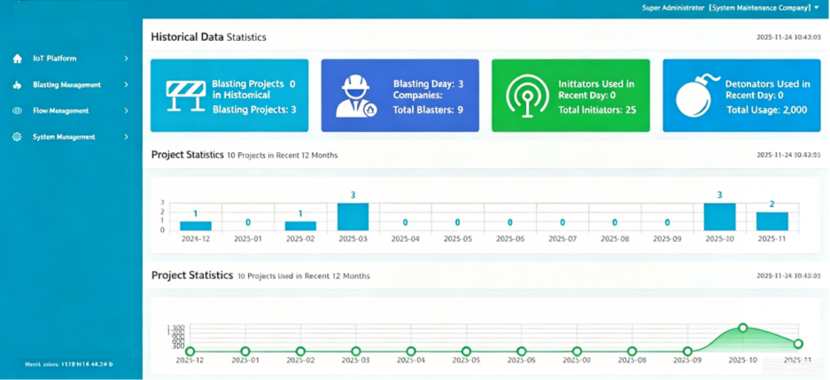
- Function Overview
After logging in, the user will see the following functions:
4、Core Advantages
- Thermite-based energetic ignition resistor: Eliminates the primer charge in the detonator, enabling direct initiation of common primary explosives such as DDNP and lead thiocyanate series.
- 13% efficiency improvement: The dipping process is removed from production; the module can be directly inserted into the primary explosive.
- 20% safety improvement: Traditional primer compounds are highly sensitive and prone to accidents during production and transportation.